Malekko Heavy Industry
Malekko VCA Dual Voltage Controlled Amplifier Eurorack Module
Malekko - Dual Voltage Controlled Amplifier
The MHIC-VCA2 implements two high fidelity, low noise, multi-mode Voltage Controlled Amplifiers in a Eurorack compliant 4 HP physical format.
Panel Functionality
The image below depicts the panel layout for the upper of the two identically operating VCA channels.
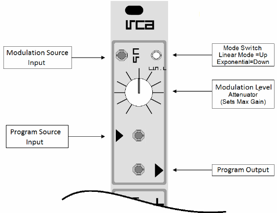
Modulation Source Input: When either an audio or control signal is routed from the Program Source Input to the Program Output jack, the signal applied to the Modulation Source Input jack controls the program level (if audio, "Volume"). Typical Modulation sources are LFO's, Envelopes, and foot pedal controllers.
Mode Switch: This panel switch controls whether the VCA responds to the Modulation Source with linear or exponential response. The Linear response being typical for VCA's, the Exponential mode provides for dynamic percussive events.
The Modulation Level: This panel control is an input attenuator. It is not uncommon for Euromodules to provide eccentric levels, especially for envelopes. The VCA is characterized for 5 Volt Modulation Sources. Sources of greater voltage swing can be attenuated to achieve proper operation for this module.
When no modulation source is jacked into the VCA, an internal voltage is normalled to the Modulation Level Control to allow manual level setting or to allow the preview of a patch configuration in progress.
The Program Source Input: Being D.C. coupled, the VCA can process either audio or control program inputs. The typical input signal range includes up to +/-5 volts inputs. Signals that exceed this level will distort. Signals exceeding +/-12 volts will damage the module.
The Program Output: VCA inputs will emit from the Program Output jack at a level directly responsive to the signal state at the Modulation Input Jack. When +5 VDC is applied to the VCA, the signal path from the Program Input to Program Output is unity gain (0 dB attenuation).
Module Architecture
The following graphic depicts the structure of the 4 HP MHIC - Dual Voltage Controlled Amplifier (VCA).
Simply stated, an AC or DC signal connecting to the Program Source Input is attenuated to a degree correlated to the signal connecting to the Modulation Source Input.
As there is no authoritative Euro-signal specification, the following assumptions/restrictions exist:
General: All signals applied to the module are assumed to be less than +/-12 Volts. Exceeding this can harm the module and voids the warranty.
Program Source Input: This input is bi-polar and assumes connecting signals range up to +/-5 Volts. Levels beyond this "clip", resulting in distortion for AC signals.
Modulation Source Input: This input is uni-polar assuming a signal range of 0 to +5 volts. As Eurosignals have no authoritative specification, a Level control attenuates signals greater than +5 volts.

Linear and Exponential Modes: The front panel mode control switch selects Linear modulation response when in the fully "up" position and Exponential response mode when depressed.
The following figure depicts the effect of a Sawtooth waveform Modulation Source upon a Triangle waveform Program Source.
The first waveform demonstrates the linear response mode where an increasing sawtooth control voltage causes a straight line increase in amplitude. The second waveform depicts the trumpet shaped exponential response to identical sawtooth modulation.

In practice this means an envelope contour that slowly changes volume when in Linear mode, produces a quick volume change in Exponential mode.
As may be imagined from the image above, if a fixed voltage is fed the to VCA Modulation Input and the input Level panel control is rotated right, the majority of the volume change occurs in the last 1/3 of the control rotation.
Mode Switching: Depending upon module signal state, switching from Linear to Exponential mode can result in an audible click.
Mode Leveling: Due to the significant difference in the response curves of Linear vs. Exponential modes and the lack of uniform specification for Euro-control signaling, a multi-turn potentiometer is provided for user adjustment of the maximum level produced in Exponential mode. The Exponential level adjustment has been factory set to allow a 5 volt DC modulation input to produce the same peak to peak voltage swing in either Linear or Exponential modes. Some users might prefer a slight increase of level for Exponential mode when its typical use is for very short duration percussive audio events.

Exponential Level Adjustment: The following graphic depicts the rear PCB location of the Exponential Maximum Gain adjustment potentiometer.
The simplest method to perform this adjustment is to apply a simple waveform such as a triangle to the Program input jack and to route the Program output to an amplifier, headset or oscilloscope.
With the Modulation input empty, adjust the panel Level control fully clockwise. Rotate the R19 screw adjustment for audible volume parity when the panel Mode switch is in Linear and then depressed into Exponential Mode. If using an oscilloscope this adjustment can be done visually.
Note:
An oscilloscope depicts peak to peak voltage where as the ear responds to apparent "power". If the modulation source is a cycling one, the ear can be fooled. If a static modulation source is input to the modulation input, ear adjustment is quite reliable.
If an external source is used to set the Modulation Level (when adjusting by ear) ensure that it is not clipping (audibly distorted). Set the intended maximum Modulation level just below the clipping.
